There are many great visual guides out there for installing a single switch region mod for the original Mega Drive, but in my searches to find one for the Mega Drive II (specifically a MD2 VA1 PAL in this case), I found mostly ancient guides and forum posts often missing images or including instructions on how to perform the more complex process of replacing the DFO as part of the mod. Since I use SCART for RGB anyway, I didn’t much care about dealing with replacing the DFO and wanted to perform the simplest possible mod to render my Mega Drive II region free.
In this post, I’ll detail the process with images for illustration, though I would like to preface this with a disclaimer that any modifications made based on what’s written here are performed entirely at the reader’s risk. I do not claim to be an expert and this modification may not work if the board differs from the one specifically mentioned.
Tools
There are a few things we’ll need for this:
- An on-off-on switch of some kind. This could be a slide switch, a toggle, a rocker—there are many options. I’m using a small toggle.
- A Phillips head screwdriver to get the console open.
- A small, sharp utility knife1 to cut a couple of traces.
- A drill or other implement to make a hole for the switch.
- A soldering iron with a relatively fine tip.
- Solder (lead free rosin-core).
- Some lengths of thin insulated wire (three different colours would be ideal).
- Something to strip the ends of the wire, e.g. wire strippers.
- (Optional) Ispropanol and some cotton buds for keeping things clean.
- (Optional) A hot glue gun for some added strength and insulation.
- (Optional) A multimeter if we want to verify that things are actually connected to each other.
- (Optional) Electrical tape to keep things tidy.
- (Optional unless we value our sight) Safety glasses.
- (Optional unless we want to live a long and healthy life) Some sort of extractor fan—these are easy to make out of a PC fan and some activated carbon filter.
- An expensive 3D printe— I’m just kidding.
Opening up the console
Getting the console open is pretty easy so I won’t bother going into too much detail. First we turn the console over and remove the base plate (if include), then unscrew the four corner screws. We can then turn it back over and remove the top to reveal the metal RFI shield. Unscrew all the small screws around the edge2 and this should lift off easily giving us unobstructed access to the circuit board itself.
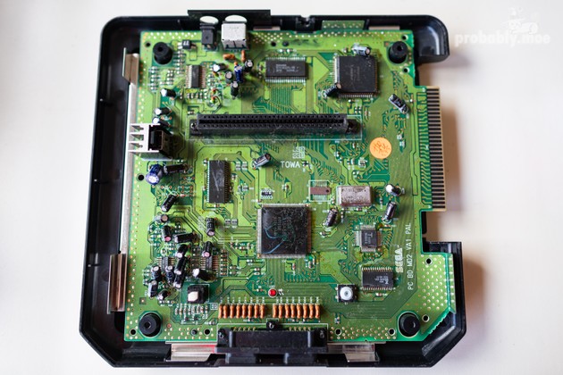
This is a good opportunity to do a quick check of each of the capacitors, making sure that none of them have started to leak or swell. Swollen domes or a brown/orange leakage are a bad sign here. If we spot any of these signs, we should probably replace them before they leak their corrosive fluids all over everything and do irreparable damage to the board. Fortunately, all of mine seem to be intact and this doesn’t seem to be a very common problem for the MD23.
Performing the modification
Let’s talk briefly about how and why this mod works at all.
We’re interested in two very specific pins on the main CPU: pin 46, which controls the vertical refresh rate, and pin 107 which controls the language. Depending on the region of the console, these two pins will be tied either to 0V (ground/GND) or 5V (logic high).
Specifically, if pin 46 receives 5V, the console will generate 60Hz, but if it receives 0V, it will generate 50Hz. If pin 107 receives 5V, the console will run in English, but if it receives 0V, it will run in Japanese. There are four possible combinations arising from this, though functionally, only three are used:
- USA (NTSC-U): English (5V), 60Hz (5V).
- JP (NTSC-J): Japanese (0V), 60Hz (5V).
- EU (PAL): English (5V), 50Hz (0V).
This mod works on the basis that if we can get the console to default to being NTSC-U (5V to both pins), all we have to do is connect GND to one of the other pins to swap to the corresponding region. This means we can attach three wires to a single switch—one to pin 46, one to pin 107, and one to GND.
As luck would have it, both pins on this board default to 5V when disconnected from their corresponding GND and 5V planes. Initially however, pin 46 is connected to GND and receiving 0V, while pin 107 is connected to 5V, so we’re going to have to start by rectifying that.
Both pins are quite easy to locate—for 107, find pin 1054 and count two pins counter-clockwise. For 46, count 6 pins clockwise back from 52. Most guides I’ve encountered suggest lifting these pins to restore their default values.
Do not do this.
Or well, you can if you really want to, but doing so without breaking the pins requires skill, or luck, or more likely both5. What we’re going to do instead is cut the traces that connect them to GND and 5V, which is significantly easier6.
If we follow the trace from pin 107, we’ll find the connection to the 5V plane.
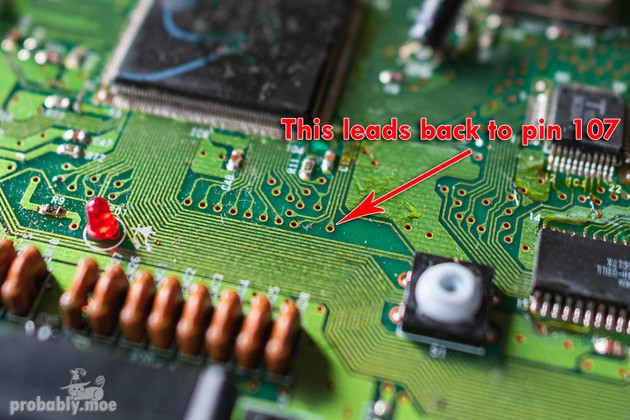
What we need to do is cut the trace just before this connection to effectively isolate the pin from the plane. We can do this very carefully with a sharp knife. I like to use a bit of isopropanol on a cotton bud to clean up the board during the process so that I can see how much progress I’ve made on the cut. We might have to dig around a bit with the blade to be sure the trace is completely cut beneath the mask, but we don’t need to go too deep to sever the connection.
Since we’re here anyway and there aren’t any convenient ways to connect our language wire to the pin, we’re going to make our own by scraping off some of the solder mask from the trace, leaving a strip of bare copper connected to pin 107 just before the small cut we made.
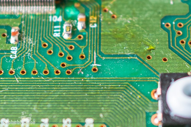
Now we need to isolate pin 46 from GND so our MD2 defaults to generating 60Hz. Unlike with 107, the trace from 467 doesn’t come to a convenient stop at one of these connections. Instead, it winds a bit along the board, connecting to GND along the way and eventually reaching a jumper point (JP3) we can take advantage of later. It’s not immediately obvious that this jumper point connects to the trace above it, but we can verify it by using a multimeter to perform a continuity test by touching one probe to JP3 and the other to pin 46.
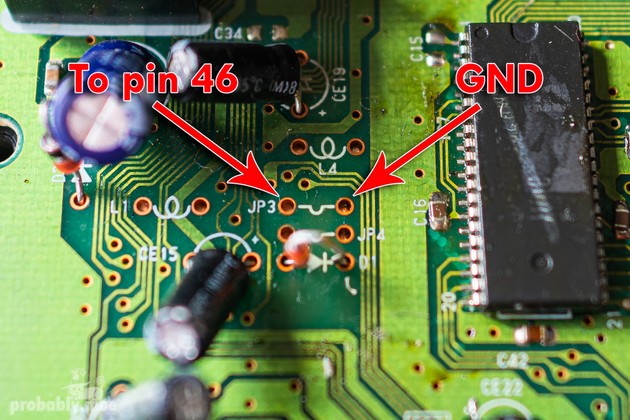
It’s good to know these are here, but we can set them aside until the time comes to solder our wires. As we were making our way here, we might have noticed the branch in the trace leading to another connection which links pin 46 to GND. We’re going to have to cut the trace here, on the branch, to disconnect pin 46 from GND and have it default to 5V.
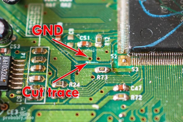
This completes the cuts we need to make and should result in the console defaulting to NTSC-U. We can stick in a region locked cartridge and start it up to verify. Alternatively, a non-region locked PAL game can work too, since many PAL games run with borders along the top and bottom at 50Hz, but will be properly full-screen at 60Hz.
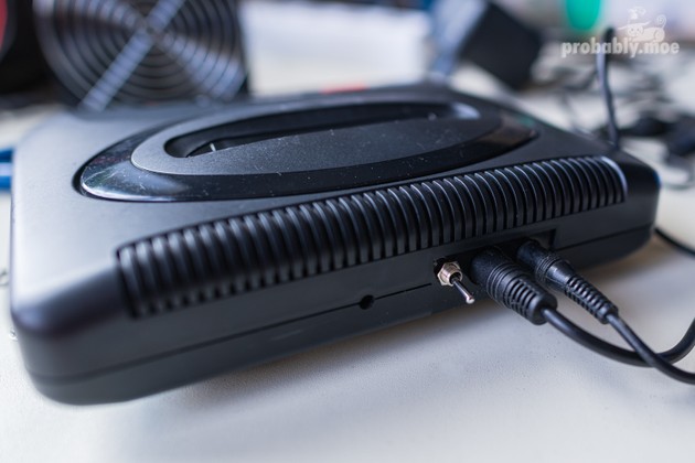
With the cuts done, we can think about where we want to put our switch. I wanted mine to be at the back of the console where it would be hidden from view most of the time. Next to the other ports seemed like a good idea.
I made a bit of a mistake here because I didn’t take into account the RFI shield which slightly blocks this spot for a switch of the size I had on hand. In theory the switch can go anywhere it won’t interfere with anything else and where the wires can reach around the RFI shield. The sides might be more practical to avoid needing to cut a chunk out of the RFI shield to get the switch in place8, but I’d already made the mistake long before reaching that point.
I strongly suggest planning any cuts in the casing far better than this.
It might make sense to remove the circuit board before making this cut9 if working with power tools. I used a hand drill so I wouldn’t have to.
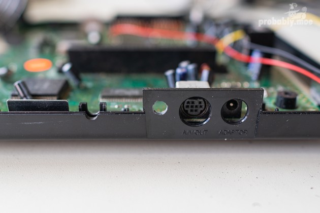
We now pick three colours of wire we’ll use to connect our switch to the two pins and GND. I chose red for language, yellow for GND, and black for refresh rate. The lengths I chose were long enough to give me some leeway to wind them through the case to where the switch would reside.
After stripping the ends to expose the inner copper threads, we first solder the red wire to the strip of copper we exposed leading to pin 107. This might be a bit tricky, but it helps to tin both the strip of copper and the wire with solder before soldering them together.
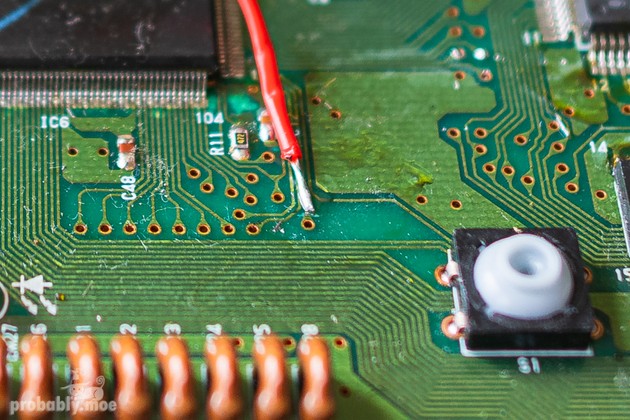
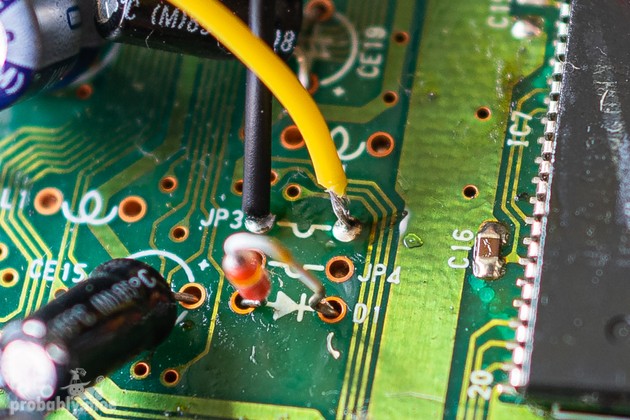
With that done, we need to solder the black wire to the jumper we spotted earlier (JP3) and the yellow wire to the GND connection adjacent to it. We can verify that it is indeed a GND connection by doing a continuity test with the multimeter between the connection and any of the ground points around the edge of the circuit board. Once we’re happy that it is, we can solder those wires through the holes in the board, dealing with any existing solder if necessary.
This is a good time to try a dry run with the switch. We can wrap the other exposed ends of the wire around the contacts on the switch and insulate them with a bit of electrical tape. The red wire goes to one side, the black to the other, and the yellow to the middle. If we boot the console in the central (off) position, we should find it’s in NTSC-U mode. Flick the switch towards the red wire’s contact and we should go into PAL mode. Towards the black will give us NTSC-J. It’s probably a good idea to verify this using carts to check region lock, language, and refresh rate.
When we’re happy it’s all working, we can solder the wires on properly—after making sure we’ve trimmed them to our desired length and figured out how they’ll sit in the case, of course.
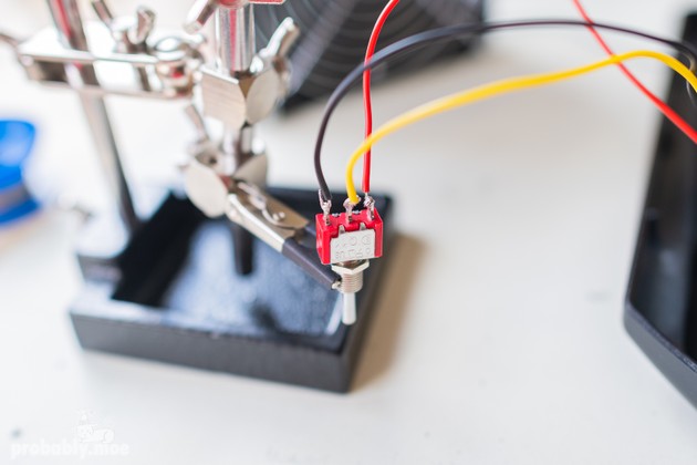
Now we can just do some final testing, hot glue up the connections for extra stability and insulation if we want to, and then slot the switch nicely into place on the case. I elected to install mine with the black cable up, so that when the switch is flipped downwards, I’ll always know it’s in PAL mode.
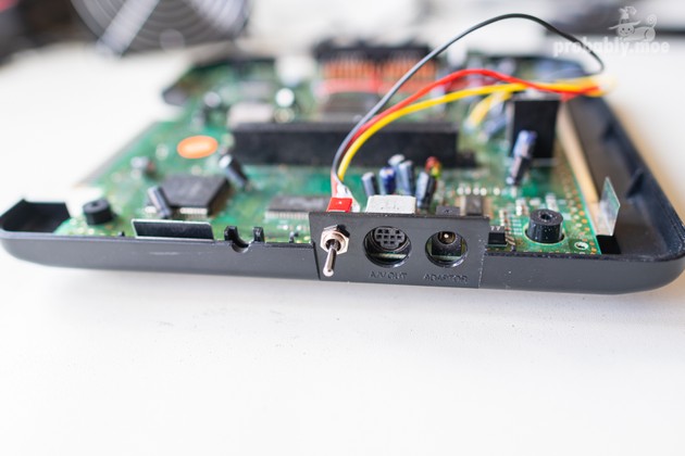
All that’s left is to seal it up. If we were smart enough to pick a place where the switch doesn’t collide with the RFI shield. Unfortunately, I was not. I had to resort to cutting a bit out of the metal so that it would fit neatly around the switch while still making contact with the GND points below it. It’s a bit of a messy solution, but it works as a worst case. I was very adamant I wanted my switch to go here. Especially after I’d already made the hole for it.
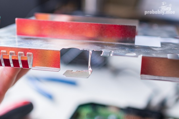
But with that unplanned modification complete, the console will finally close. We can refasten the RFI shield and screw it back down. Affix the top half of the casing, flip it, screw that in, and reattach any base plate as necessary. From the outside, this should leave us with a pretty tidy looking switch, hidden away in an unobtrusive spot.
I personally chose not to file down the tabs on the cartridge slot10 in favour of using a cartridge adapter for Japanese games instead. Even if it’s not a particularly noticeable change, I still feel it would negatively affect the aesthetics of the front of the console.
One last quick check and I’m happy that everything seems to be working as it should. Three regions. One switch. And not nearly as complicated as trying to go switchless.
-
Like an X-Acto knife.
↩ -
Making sure to keep them separate from the first set so we don’t get them confused.
↩ -
The same cannot be said of the Mega CD2 in which it apparently occurs quite frequently.
↩ -
The corner pins are numbered.
↩ -
Neither of which I would claim to possess.
↩ -
And won’t ruin the entire board if messed up.
↩ -
We find 46 by counting back clockwise from pin 52, if you recall.
↩ -
Assuming the switch even fits, which the sliding kind might not.
↩ -
I didn’t, but then I’m often not smart.
↩ -
As would be required for the rounded Japanese carts to fit.
↩
